Controlling MRG LFOs frequency range

The MRG LFOs contains two different oscillator cores, each capable of oscillating from slightly more than a second to about 600Hz.
Deciding the frequency range of an LFO is a matter of components selection, arbitrary decisions, physical limits and personal taste.
There are three components that control the timing of each LFO in the circuit:
- The resistance at the 1M potentiometer (Rp) in the front PCB.
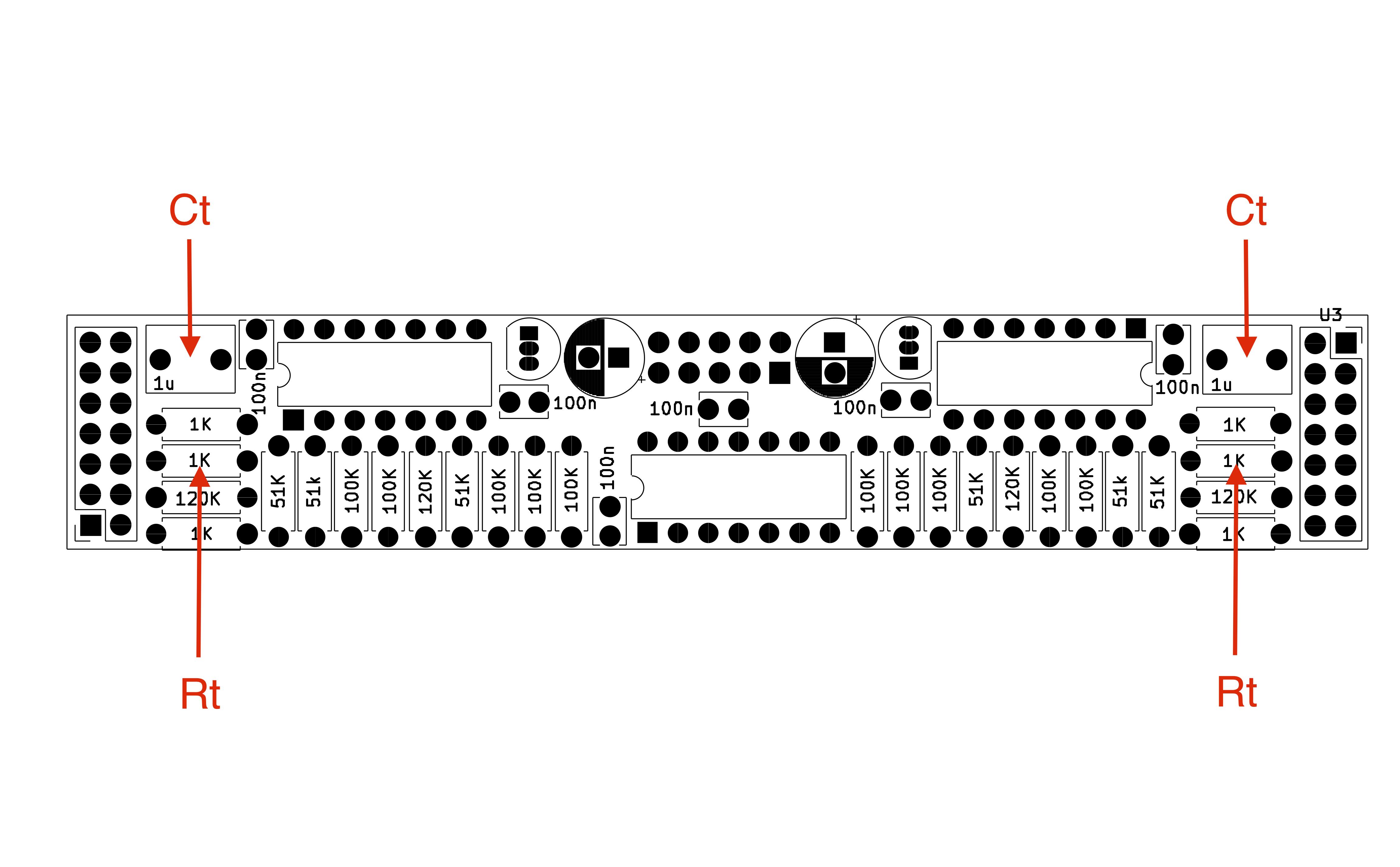
- The resistor (Rt).
- The timing capacitor (Ct)

Location of the components controlling the frequency range on a MRG LFOs PCB. Click Here for full picture.
The mathematical relationship that regulates each LFO frequency is:

The highest frequency is realised when the potentiometer is at its minimum, and can be approximated by removing Rp from the equation:

and the lowest when the potentiometer is at its maximum, approximated by exchanging Rp with the value of the potentiometer:

The MRG LFOs as shipped and designed uses 1K for Rt and 1uF for Ct, creating the following theoretical frequency ranges:


In general, these default frequency ranges can be changed by modifying the elements involved. The suggested way of doing that is changing the timing capacitor Ct. A bigger capacitance will make the oscillator slower, a smaller one faster.
As long as the timing capacitor Ct is a non-polarised capacitor with a 5mm pitch, it should be fine. Of course, being a timing capacitor, the suggestion is to use a film capacitor, although 5mm pitch film capacitors at the micro-farad scale are unfortunately rare.
Using a Ct of 4.7 uF as a timing capacitor leads to the following minimum and maximum frequencies:


Of course, as everything analog these are approximations, and real life measurement will be subject to some degree of error.
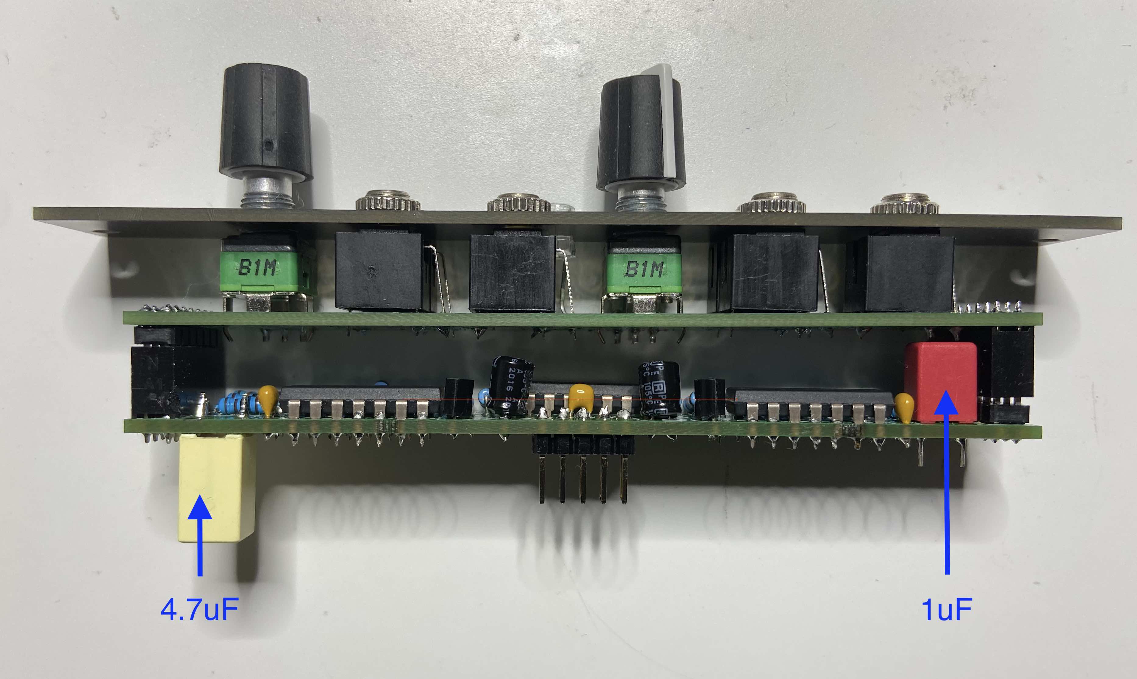
As an example, the picture below shows a MRG LFOs modified with a 4.7 uF capacitor in one of the oscillators (I am using the KEMET R82CC4470Z330K ). The measured frequency range was from .126 Hz (about 8 seconds) to 124Hz.
