MRG KICK (2nd gen) Assembly Guide
Theory of operation:
- If you bought the PCB+Panel only, acquire needed components (See Bill of Materials . All components used in this guide are already included in the full DIY kit.
- Build the Main PCB.
- Build the Front PCB.
- Install the front panel.
Main PCB build

Step A1. Solder the four transistors. Be careful of not to short their pins. Flux, as always, is highly suggested.

Step A2. Solder the 10-pin header Eurorack connector.

Step A3. Turn the board again and solder the three transistors, using the same care used in step A1. If you want to use an IC socket (14 pins) instead of soldering the IC directly at the end, solder it now.

Step A4. Solder the film capacitors and the two 22uF electrolytic capacitors.

Step A5. Turn the board again and solder the 33uF electrolytic capacitor.

Everything apart from the two 14-pin headers are soldered on the board now. It is time to solder the front PCB.
Front PCB Build
Step B1. Check the alignment of the PCB (label U1 is the top row), arrange the jack sockets and the potentiometers. Be careful on placing the B1M at position U4. Do not arrange nor solder the LED for now.

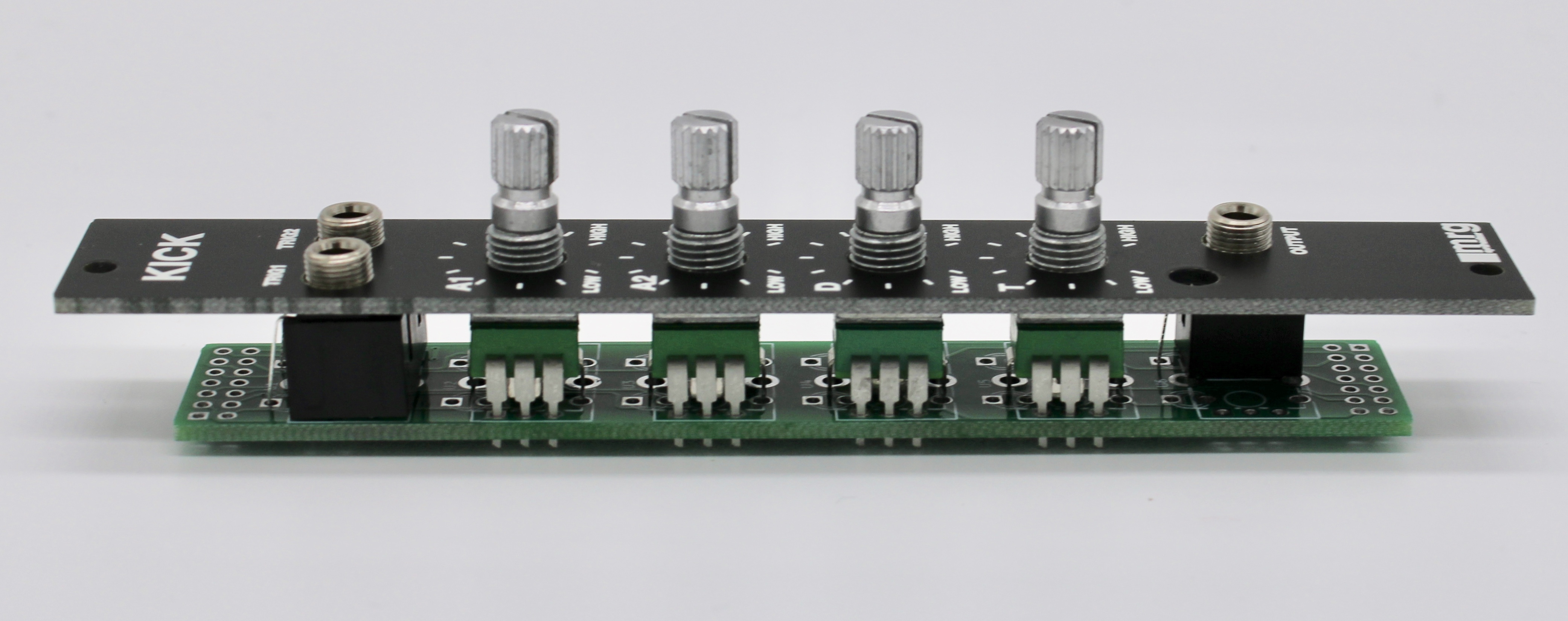
Step B2. Solder the components. Tip: in order to be sure to align the components to the front panel, install the front panel as in photo below and solder the components on the back.
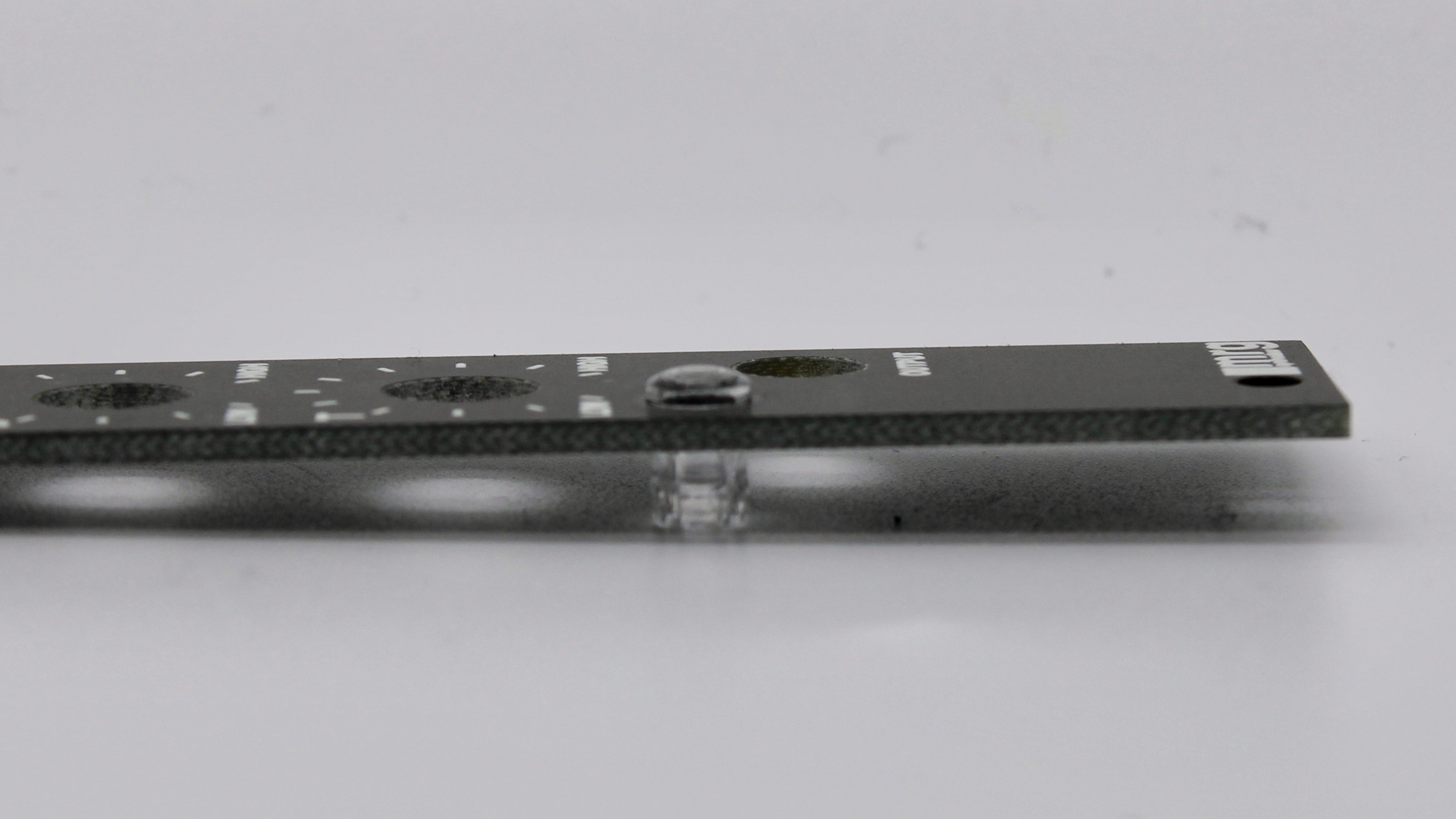
Step B3. Install the LED cap in the panel. Firmly press the cap on the panel until it clicks in.
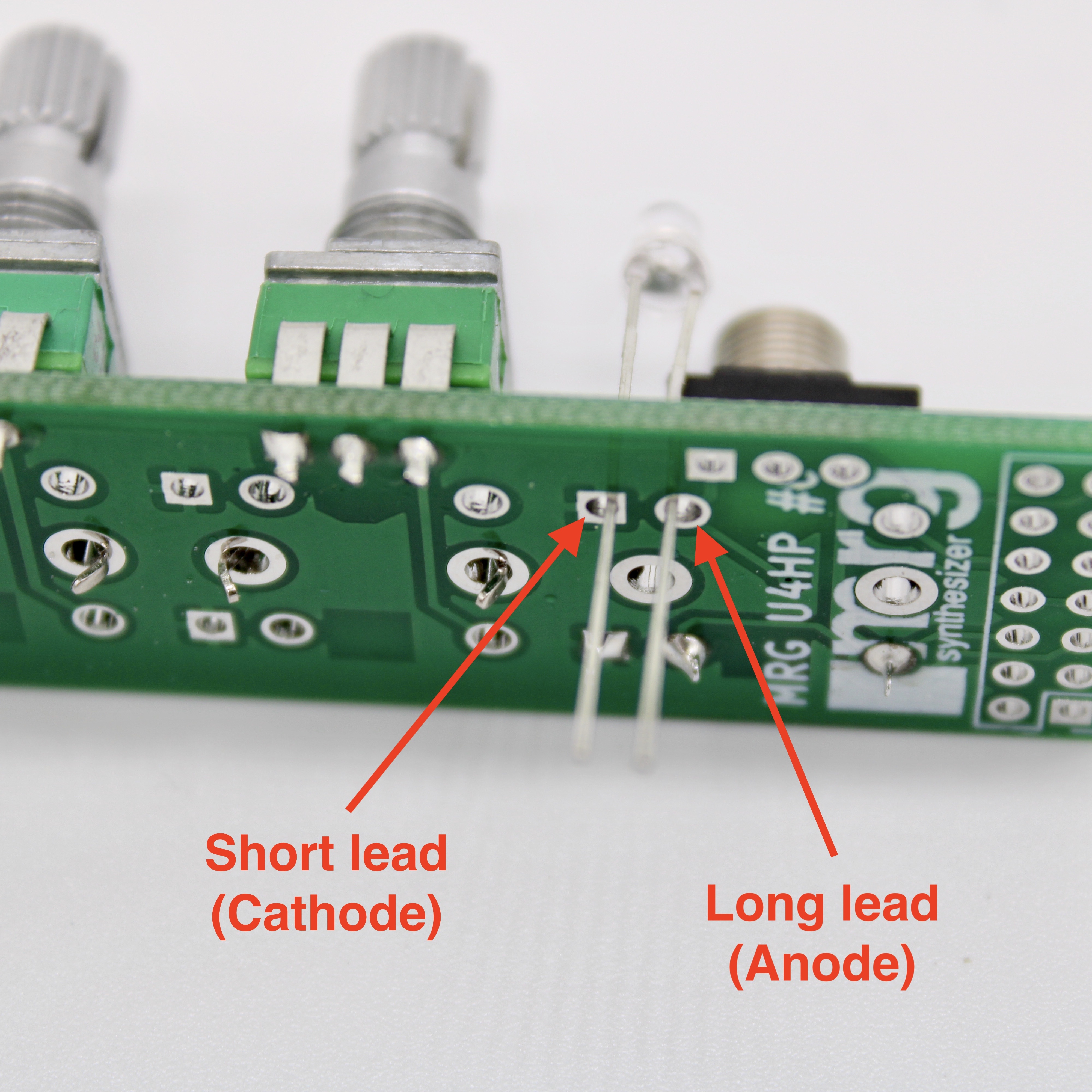
Step B4. Insert the LED as shown in picture. Doublecheck that the short lead is up.
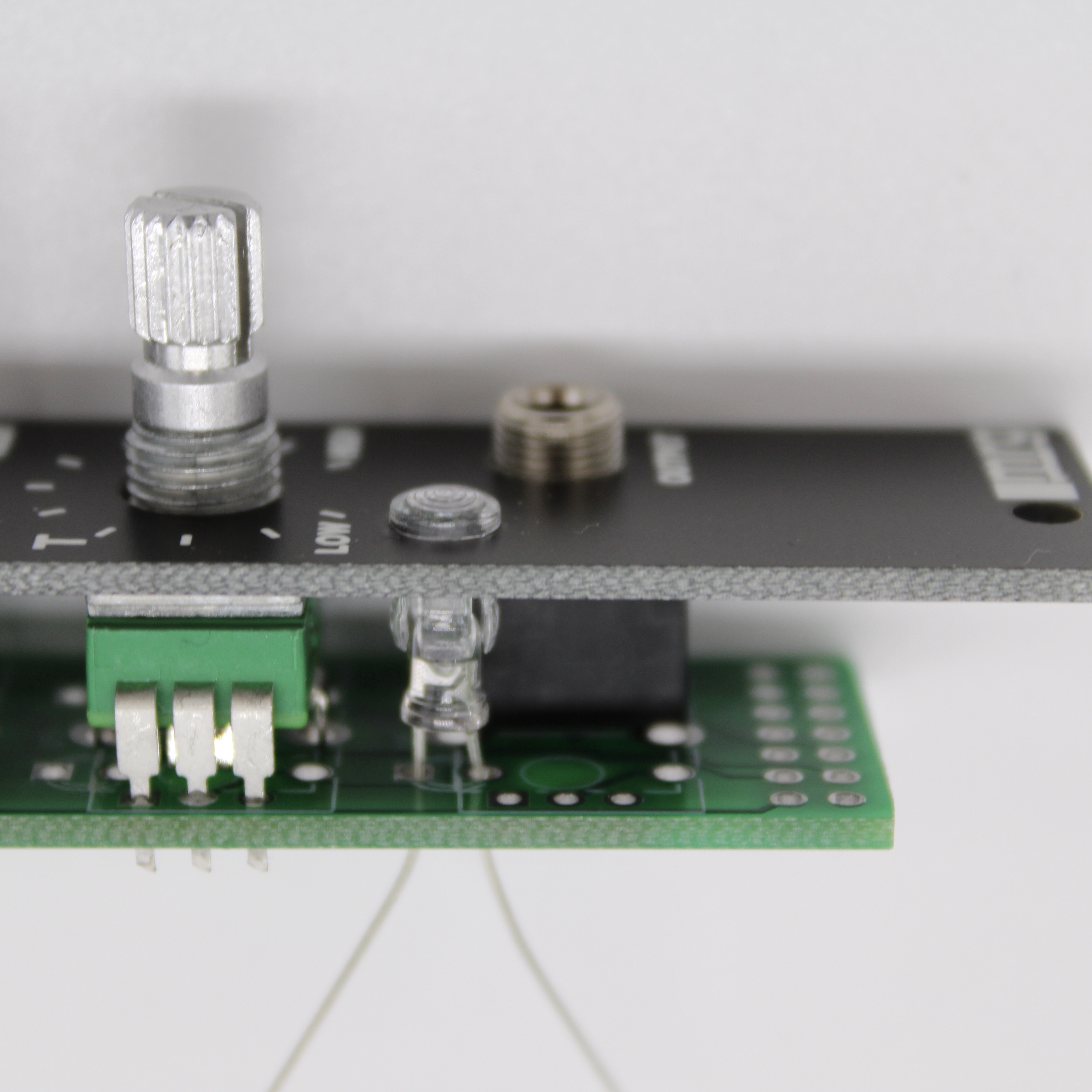
Step B5. Insert the panel again, and check that the LED is fully inserted into the cap. Solder the LED in place.
Step B6. Solder the socket headers. Tip: In order to align the Main PCB’s pin headers to the Front PCB’s socket headers, assemble the two PCBs together, as in picture, and solder them in place. Note that the two MRG logos are aligned at the bottom of the module on both PCBs.
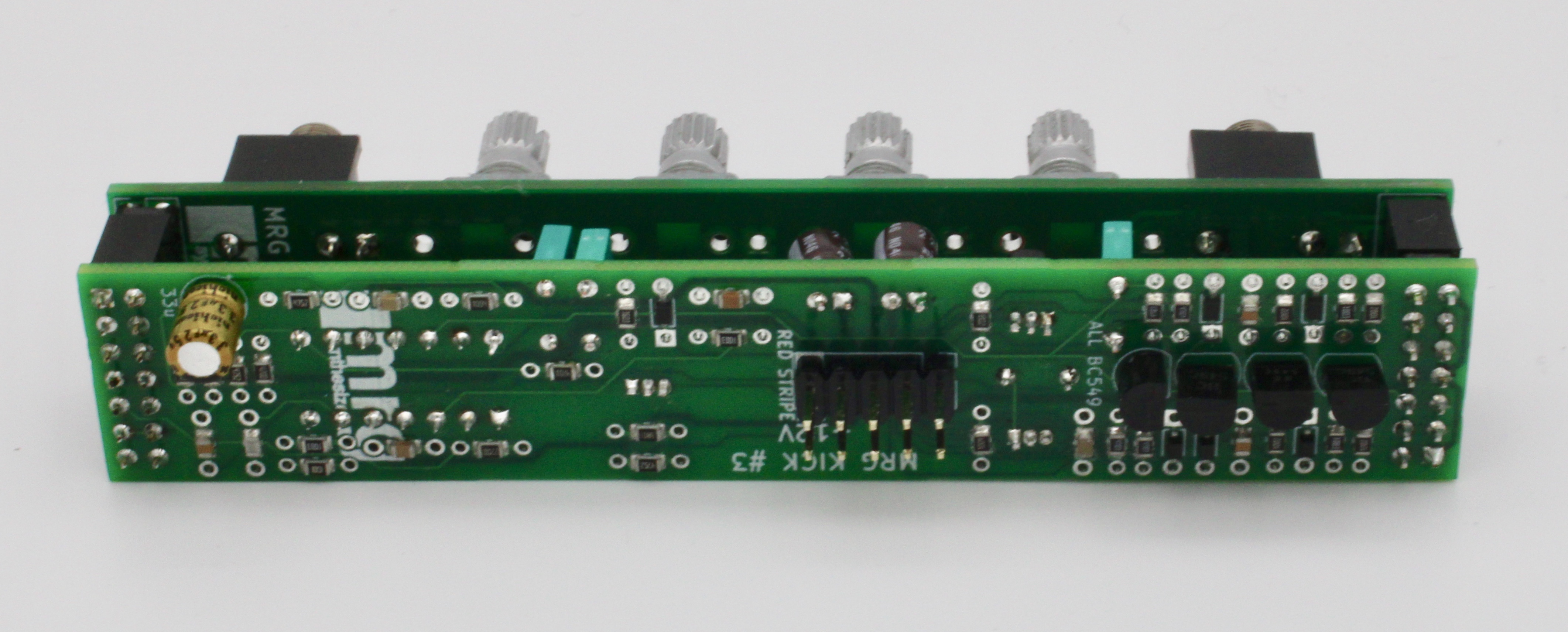
Congratulations! The build is nearly done.
Final Module Assembly
Step C1. Insert the IC in the socket. If you haven’t used an IC socket, solder the IC now.

Step C2. All that’s left now is to install the front panel, using nuts and washers to keep it attached, and adding the knobs to the potentiometers.

Feedback? Suggestions? Contact me! .